CI Topology
Overview
CI Topology visualizes the relationship network between configuration items. It provides two modes — Graph View and Table View — that can be toggled with a single switch at the top. It appears in multiple modules: CI Topology View, the query preview in Query Studio (both driven by a query definition), the "Configuration Topology" tab of the CI Directory (based on a single CI), and others — the behavior is largely the same everywhere.
- Graph View: Behavior is consistent across entry points; this page covers the common operations below. Query-definition entries (CI Topology View, Query Studio query preview) additionally offer root node filtering (switch the visible scope by the root node instance of the query). See each module's own documentation for details.
- Table View: The right side is the unified data table (see Common Data Table Operations for column management, filtering, pagination, density, and more); however, the left-side navigation varies by module: query-definition entries (CI Topology View, Query Studio preview) show the topology structure of the query definition, while single-CI entries (the main CI Directory interface) show the CI type tree. Therefore, the left-side layout and export scope of the table view are described in each module's own documentation.
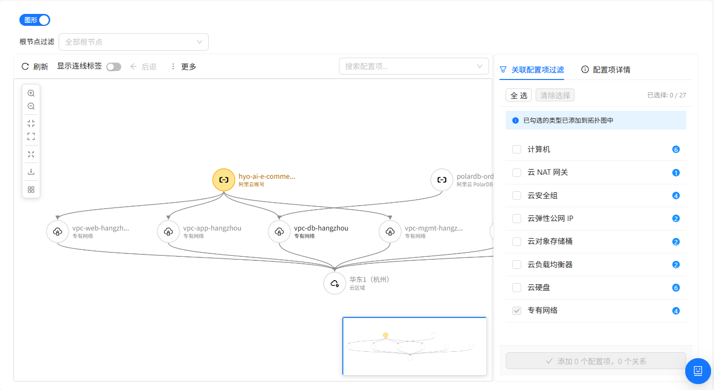
Graph View
Graph View renders CI instances as an interactive relationship network: each node is a CI instance and each edge is a relationship between two CIs. The overall layout is split into left and right panes: the left is the topology canvas, and the right shows a "Related CI Filter" (referred to below as the Explore Panel) and a "CI Details" panel (the Details Panel) on demand when a node or relationship is selected.
Canvas Operations
The canvas provides two toolbars: a floating toolbar in the upper-left corner (vertical, grouping zoom and export actions) and a fixed toolbar along the top (horizontal, grouping navigation, edit, and search actions).
Floating Toolbar (upper-left of canvas)
| Operation | Purpose | When to use |
|---|---|---|
| Zoom In / Zoom Out | Adjust the canvas scale | To see node details / to survey the overall structure |
| Fit to Canvas | Auto-fit so all nodes are visible and fill the canvas | Quickly return to the global view after nodes get scattered or over-zoomed |
| Actual Size | Center the view at the current scale | Return to a stable, centered perspective |
| Fullscreen | Switch to immersive browser-fullscreen mode | Presenting the relationship network to colleagues or leadership |
| Download Image | Export the current topology as a PNG | Pasting into ops reports, incident reviews, or architecture docs |
| Switch Layout | Switch between four auto-layout algorithms | When the default layout doesn't reveal hierarchy, try another (see table below) |
Available layout algorithms:
| Layout | Characteristics | Suitable for |
|---|---|---|
| Vertical Hierarchical (default) | Root at top, expanding layer by layer downward | Showing upstream/downstream dependency chains |
| Horizontal Hierarchical | Root on the left, expanding rightward | Showing left-to-right data or call flow |
| Force-Directed | Nodes distribute by attraction; densely related nodes cluster together | Discovering "cluster" structures in the network |
| Concentric | Nodes arranged on concentric rings | Evenly distributed ring-style presentation |
Fixed Toolbar (top of canvas)
| Operation | Purpose | When to use |
|---|---|---|
| Refresh | Re-fetch current topology data | When data may have changed or a CI was just modified elsewhere |
| Show Edge Labels toggle | Show/hide the relationship-type label on each edge | Turn on to clarify which relationship each edge represents; turn off when it feels cluttered |
| Back / Forward | Move between exploration-history states | Step back after a mistake in Explore mode, or step forward after going back too far |
| Link Existing CI | Link an existing CI to the currently selected node | Recording a relationship between two existing CIs (requires full CI access permission) |
| Create Related CI | Create a new CI and simultaneously establish a relationship with the selected node | When a downstream CI is missing and you want to create and attach it in one step (requires full CI access permission) |
| Delete | Remove the currently selected node or relationship | When a CI or relationship is deprecated and should be removed from the topology (requires full CI access permission) |
| Search CI (dropdown on the right) | Locate a node by name within the current topology | When there are many nodes and you want to focus on a specific CI |
When the window is narrow and the toolbar cannot fit all buttons, some buttons fold automatically into a "More" dropdown at the end. Click "More" to use them — the functionality is identical to when the buttons appear directly on the toolbar.
Node Operations
Each node represents a CI instance.
| Operation | Description | How to |
|---|---|---|
| Quick Preview | Hover popup showing name, type, and key attributes | Hover over a node (no click needed) |
| Select Node | Highlight the node and show the details/explore panel on the right | Click the node |
| Locate Node | Pan the selected node to the canvas center and zoom in | Pick a target from the "Search CI" dropdown on the right of the toolbar |
| Drag Node | Freely adjust the node's position on the canvas | Press and hold the node, then drag it to the target position |
| Edit Node Attributes | Modify and save attributes in the right details panel | Select the node → edit in the right panel → save (requires full CI access permission) |
| Delete Node | Remove the CI from the topology (and the system) | Select the node → click "Delete" in the toolbar (requires full CI access permission) |
Node Search
The "Search CI" dropdown in the upper-right of the canvas is used to quickly locate a node within the current topology:
- Type a keyword into the dropdown
- The system matches by CI name and lists candidate nodes
- After selecting a candidate, the canvas highlights the node and pans to focus on it
Node search looks only within the nodes currently loaded into the graph. If the CI you are looking for is not yet on the canvas, first add it via Explore Mode.
Edge Operations
Each edge represents a relationship between two CIs.
| Operation | Description | How to |
|---|---|---|
| View Relationship Details | Show source, target, type, and other information in the right panel | Click an edge |
| Delete Relationship | Delete this relationship between the two CIs | Select the edge → click "Delete" in the toolbar (requires full CI access permission) |
When the "Show Edge Labels" toggle is on, each edge is labeled in its middle section with the relationship type it belongs to (for example, "runs on", "depends on"), making the semantics of each relationship quick to understand.
Explore Mode
Explore Mode is a way to progressively expand the topology starting from a single node. It is well suited for focusing on critical paths within a large relationship network.
Basic Flow
- Click a node of interest on the canvas
- The Explore Panel opens on the right, listing the types of CIs the node can be related to (grouped by type)
- Check the specific instances you care about within each group (supports "Select All" / "Clear Selection")
- Click the "Add" button at the bottom; the selected instances — along with their relationships to the current node — are appended to the canvas
- Repeat these steps to keep expanding outward from newly added nodes
Explore Panel Reference
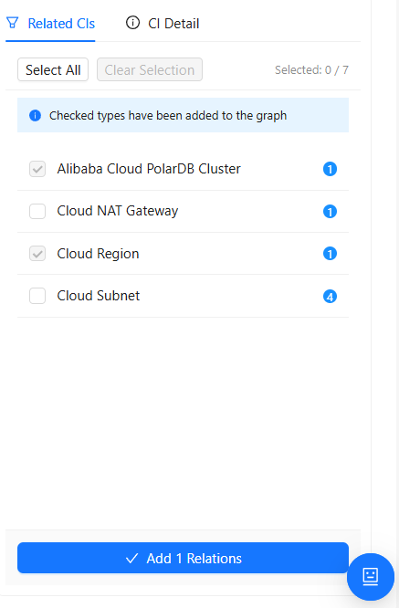
| Area | Purpose |
|---|---|
| Related CI Types | Lists all CI types directly related to the current node — for example, "runs on → Computer", "depends on → Application" |
| Related Instance Data + Checkboxes | Each related CI type shows the count of related CIs on the right and a multi-select checkbox on the left. Use "Select All" or "Clear Selection" to bulk-check or clear all related CI types |
| Selected Count | Live display of "Selected X / Total Y" so you can gauge the size of your selection |
| Add Button | Appends all checked instances — and their relationships — to the topology graph |
When every candidate instance of a type has already been added to the canvas, the checkbox to its left is automatically selected and made read-only to prevent duplicate additions. To return to the pre-add state, use the History Navigation feature.
History Navigation
Every topology expansion is recorded in history. The "Back" and "Forward" buttons in the toolbar let you switch between history states:
- Back: Return to the state before those nodes were appended
- Forward: Re-apply the state that was just backed out of
Node Limit
To protect rendering performance, the topology graph enforces a maximum-node limit (default 500, controlled by the system setting Topology Graph Node Limit — generally an admin with system-settings permission is required to change it):
- When appending would push the total past the limit, the system performs a partial append and prompts: "Only X of the selected nodes were added."
- When the total already reaches the limit, no further appends are allowed and the system prompts: "The topology graph has reached the maximum number of nodes."
If you need to view data beyond the limit, switch to Table View (see each module's documentation).
Relationship Maintenance Operations
The following operations require full CI access permission. If the buttons are not visible, your current account lacks the permission.
Link an Existing CI
Attach an already-existing CI to the currently selected node to establish a new relationship:
- Select a node on the canvas
- Click the "Link Existing CI" button in the toolbar
- In the "Link Existing CI" dialog, search for and select the target CI
- Choose the relationship type
- Confirm — the new relationship is established immediately and a new edge appears on the canvas
Create a Related CI
Create a new CI and simultaneously establish its relationship with the current node:
- Select a node on the canvas
- Click the "Create Related CI" button in the toolbar
- In the "Create Related CI" dialog, choose the target CI type and the relationship
- Fill in the required attributes
- After saving, the new CI automatically appears on the canvas, connected to the current node
Delete a Node or Relationship
- Select the node or relationship to delete
- Click the "Delete" button in the toolbar
- Click "OK" in the confirmation dialog
Deleting a node removes the CI instance from the system entirely (not just hiding it from the current canvas). Confirm before proceeding. Deleting a relationship only disconnects the two CIs — it does not delete the CIs themselves.