Query Details
Overview
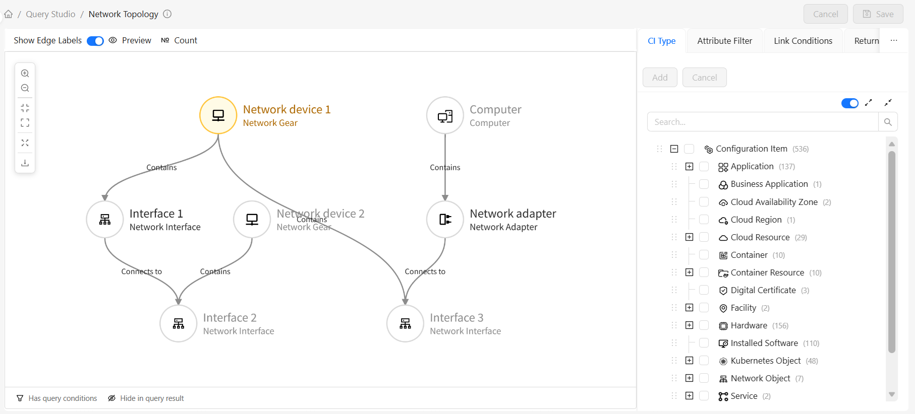
The Query Details page is the core workspace of Query Studio, providing a visual topology query editor. You can graphically define query topology structures, configure filter conditions, set return attributes, and more.
The detail page uses a left-right split layout:
- Left: Query topology graph, visually displaying query nodes and their connections
- Right: Configuration panel with multiple tabs for configuring different aspects of the query
Configuration Panel
The configuration panel contains the following tabs:
- CI Types: Add selected CI types as query nodes to the left topology graph
- Attribute Filter: Configure attribute filter conditions
- Link Conditions: Configure connection relationships between nodes
- Return Attributes: Configure attribute fields returned by the query
- Type Filter: Configure subtype inclusion rules
Topology Graph Operations
Adding CI Types as Query Nodes
Method 1: Drag and Drop
- Find the desired type in the type tree in the CI Types tab
- Hold the left mouse button and drag the type node to the left topology graph area
- Release the mouse to complete adding
Method 2: Add from Type Tree (supports batch adding)
- Check the desired CI types in the type tree in the CI Types tab
- Click the Add button
- CI types are added as new nodes to the topology graph
Creating Connection Relationships Between Nodes
- Move the mouse over the source node, hold the left button and drag a line from the source node to the target node
- In the popup relationship selection dialog, select the relationship type
- Click OK to complete relationship creation
Node Operations
Right-click a node to open the context menu:
| Operation | Description |
|---|---|
| Set as Root Node | Set the current node as the query's root node |
| Show CI Instances | View the CI type's instance list |
| Change Node Type | Change the current node's CI type to another type; may require cascading changes to connections with other query nodes |
| Rename | Modify the node's query identifier |
| Hide in Query Result | Control whether the node returns results in query output |
| Delete | Remove the node from the query |
Query Root Node
The Query Root Node is the entry point of a topology query, determining the traversal starting point of the entire query. Each query has exactly one root node. In the topology graph, the root node is visually distinguished from other nodes with a special theme style (amber border).
Business Significance
The root node determines "where the query starts." The query engine uses the CI instances corresponding to the root node as the starting point, traverses outward layer by layer along your defined connection relationships, and ultimately organizes all related instances into a complete topology graph for the result. Therefore, the root node is typically chosen as the "primary object" of greatest business interest.
For example: In a "Computer Software and Hardware Inventory" query, setting Computer as the root node means the query results are centered on each computer, then expanding to its associated disks, installed software, IP addresses, and other information. If you instead set Installed Software as the root node, the results would be centered on each software license, reverse-associated to the computers that have it installed.
Default Behavior
- Auto-assignment: The first node added to an empty query automatically becomes the root node — no manual setup required.
- Auto-promotion: When the current root node is deleted, the system automatically promotes the first remaining node as the new root node, ensuring the query always has a root node.
Changing the Root Node
When business needs require a different starting point to organize query results, you can manually change the root node:
- Right-click the node you want as the new entry point in the topology graph
- Click Set as Root Node in the context menu
- That node immediately becomes the new query root node, and the original root node automatically becomes a regular node
Choosing the most natural "primary object" from a business perspective as the root node makes query results easier to understand. For example: use "Server" as the root node for server asset statistics; use "Core Switch" as the root node for network troubleshooting; use "Application" as the root node for application dependency analysis.
Relationship with Query Validation
The root node is the baseline for query connectivity validation. When saving a query, the system checks the entire topology starting from the root node:
- Connectivity: All non-root nodes must be reachable from the root node via "must exist" connection paths. Otherwise, the query graph is disconnected and the save will be blocked.
- Reachability Warning: When a node can only reach the root node via "possible connections" or "does not exist connections," or when the logical relationship between multiple link conditions is "OR," the system will issue a warning: such nodes may not be associable with the root node in the final query results.
For specific validation rules and warning details, see the Query Validation section below.
Edge Operations
Right-click an edge (relationship) to open the context menu:
| Operation | Description |
|---|---|
| Hide in Query Result | Control whether the relationship returns results in query output |
| Change Relationship Type | Modify the relationship type |
| Delete | Remove the relationship from the query topology |
CI Types
Overview
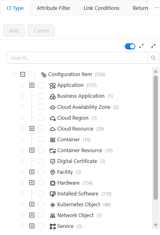
The CI Types tab manages the CI types included in the query. You can select and add CI types from the type tree to the query.
Type Tree Features
The type tree displays all CI types in a hierarchical structure:
- Expand/Collapse: Click the arrow before a node to expand or collapse subtypes
- Search: Enter keywords in the search box to quickly locate types
- Multi-select: Check the checkbox before types for multiple selection
- Drag: Hold a type node to drag it to the topology graph
- Hide Empty Types: When selected, only show CI types with CI instances in the tree
Operations
- Select Types: Check the CI types to add
- Add: Click the Add button
- Cancel Selection: Click the Cancel button to clear selection
- Hide Empty Types: Check the checkbox above the CI type tree
Attribute Filter
Overview
The Attribute Filter tab configures node attribute filter conditions. By setting attribute filter conditions, you can precisely control which CI instances are returned by the query.
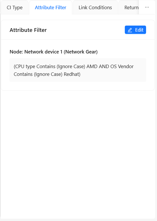
Click the Edit button to configure attribute filter conditions in the popup. For detailed configuration, see Attribute Filter Configuration. After configuration, you can see a summary of attribute filter conditions in the tab for quick understanding and verification.
Link Conditions
Overview
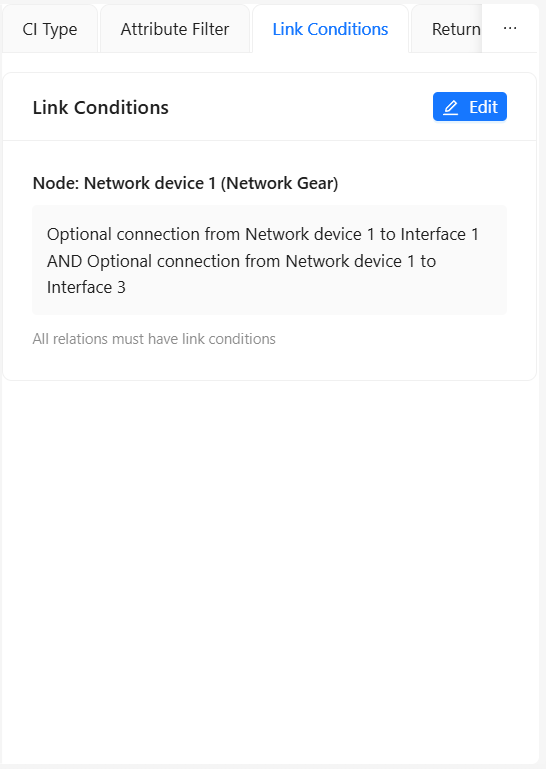
The Link Conditions tab configures connection relationships between query nodes. Link conditions determine how the query traverses from one node to related nodes.
Link Condition Types
| Condition Type | Description | Use Case |
|---|---|---|
| Exists | A connection from source to target must exist | Query CIs that must have this relationship |
| Not Exists | A connection from source to target must not exist | Exclude CIs that have this relationship |
| Optional | Connection may or may not exist | Optional relationship query |
Steps
- Select the node to configure in the query topology graph
- Switch to the Link Conditions tab
- View all link conditions for the current node
- Click the Edit button to modify link conditions:
- Select logical combination method (AND/OR)
- Set condition type for each relationship
- Add or remove relationship conditions
- Click Save to apply changes
Complex Link Conditions
For nodes with multiple relationships, you can use logical combinations:
- AND: All conditions must be satisfied
- OR: At least one condition must be satisfied
After configuration, you can see a summary of link conditions in the tab for quick understanding and verification.
A query node's link conditions must correspond one-to-one with the node's edge count, i.e., each edge must have exactly one link condition definition.
Return Attributes
Overview
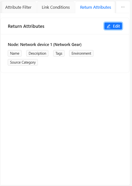
The Return Attributes tab configures the attribute fields returned in query results. By properly configuring return attributes, you can reduce data transfer and improve query performance.
Return Modes
| Return Mode | Description | Use Case |
|---|---|---|
| No Attributes | Query results contain no attribute fields, only basic CI identification information | Only need CI ID and type, no specific attribute values |
| All Attributes | Return all attributes for the type (default) | Need complete information, or attribute count is small |
| Include | Return only selected attributes | Only care about specific fields, reduce data transfer |
| Exclude | Return all attributes except selected ones | Exclude irrelevant or sensitive fields |
Configuration Steps
- Select Type in the Return Attributes tab
- If selecting
IncludeorExclude, check the corresponding attributes - After configuration, see a summary of return attributes at the bottom of the tab for quick understanding and verification
Configuration Examples
Scenario 1: Return Basic Info Only
| Setting | Value | Description |
|---|---|---|
| Return Mode | Include | Return only selected attributes |
| Selected Attributes | Name, Primary IP Address, Serial Number | Return only these three attributes |
Scenario 2: Exclude Sensitive Information
| Setting | Value | Description |
|---|---|---|
| Return Mode | Exclude | Exclude selected attributes |
| Selected Attributes | Password, Email Address | Exclude sensitive fields |
Scenario 3: Only Need Instance List
| Setting | Value | Description |
|---|---|---|
| Return Mode | No Attributes | Return identification info only |
| Selected Attributes | — | No attributes to select |
Type Filter
Overview
The Type Filter tab configures whether the query includes subtypes of CI types. CI types in CMDB typically have inheritance relationships. Type filter determines whether the query includes instances of subtypes.
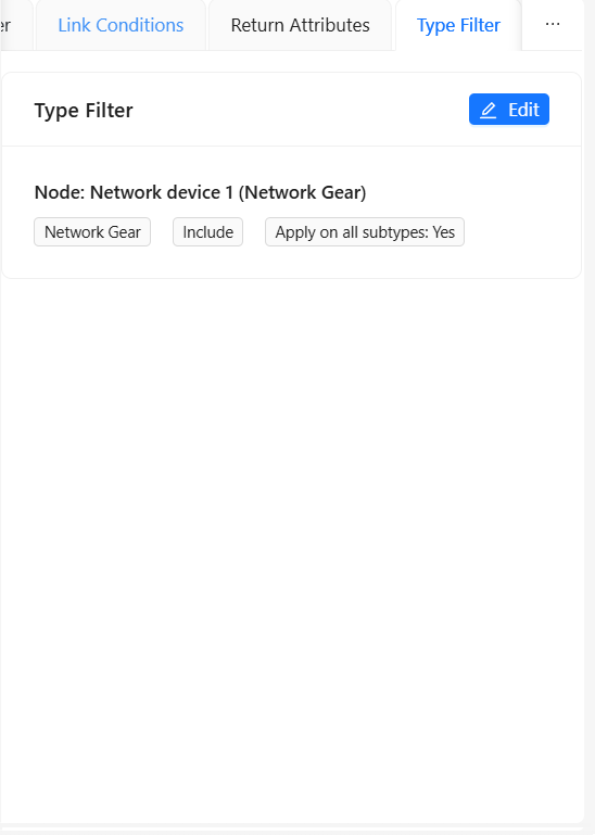
Click the Edit button on the Type Filter tab to edit type filter conditions in the popup. For detailed configuration, see Type Filter Configuration. After configuration, you can see a summary of type filters in the tab for quick understanding and verification.
Query Preview
Overview
Query preview lets you view the execution results of the current query definition before saving, validating that the query logic is correct. The preview results are consistent with what the CI Topology View displays based on the query definition, also providing both Graph View and Table View modes with identical operations.
Steps
- After completing query configuration
- Click the Preview button in the topology graph toolbar
- View query results in graph view or table view in the preview dialog
- Adjust query configuration based on preview results
Preview Views
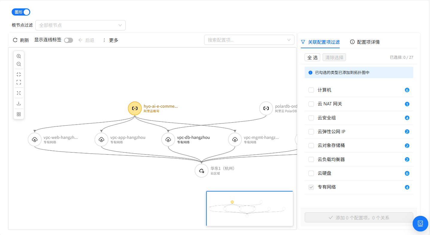
The operations for both views in the preview are identical to those in the CI Topology View. See:
- CI Topology: Common operations for Graph View (canvas, nodes, edges, Explore Mode, history navigation, relationship maintenance, etc.)
- CI Topology View Details: Features specific to query-definition-based entry points, including Graph View Root Node Filter and Table View (left side shows the topology structure graph defined by the query)
Query Count
Overview
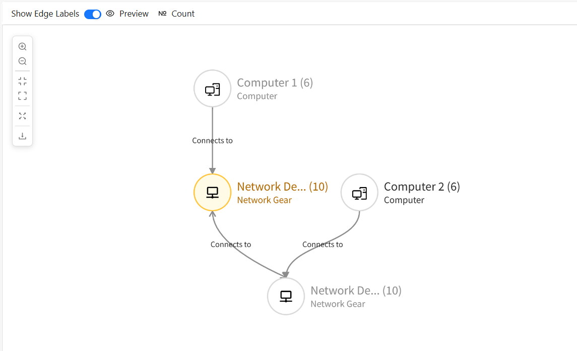
Query Count displays the number of instances each node in the query will return, helping you assess the data scale of the query.
Steps
- After completing query configuration
- Click the Count button in the topology graph toolbar
- The system displays the instance count for each type on each node
- Optimize query conditions based on statistics
Query Validation
Connectivity Validation
The system automatically validates the query graph's connectivity:
- All nodes must be reachable from the root node
- Isolated nodes or relationships are not allowed
If the query graph is not connected, an error message is displayed when saving. You need to:
- Check for isolated nodes
- Add missing relationship connections
- Or delete unnecessary nodes
Query Examples
The product includes multiple system query examples to help you understand TQL query definitions. Below are two typical query examples:
Example 1: Computer Software and Hardware Inventory Query
Business Need: Comprehensively understand computers and their associated software and hardware resources. Use this query when you need to count all computers' hardware configurations, see what software is installed on each computer, and generate IT asset reports.
Steps:
-
Create Query:
- Click "Create Query" button
- Enter query name: "computer-software-inventory"
- Enter display name: "Computer Software and Hardware Inventory"
- Select query group
-
Add CI Types:
- Find and check the following types in the type tree:
ComputerInstalled SoftwareDiskFile SystemDigital CertificateIP AddressNetwork AdapterEndpointApplication
- Click "Add" button
- Find and check the following types in the type tree:
-
Create Relationships:
- Drag from Computer node to Installed Software, select
Containsrelationship - Drag from Computer node to Disk, select
Containsrelationship - Drag from Computer node to File System, select
Containsrelationship - Drag from Computer node to Digital Certificate, select
Usesrelationship - Drag from Computer node to IP Address, select
Usesrelationship - Drag from Computer node to Network Adapter, select
Containsrelationship - Drag from Computer node to Endpoint, select
Providesrelationship - Drag from Application node to Computer, select
Depends On and Runs Onrelationship
- Drag from Computer node to Installed Software, select
-
Configure Link Conditions:
- Select Computer node, switch to "Link Conditions" tab
- Set all relationship condition types to
Optional
-
Configure Return Attributes:
- Select simple mode, return all attributes
- Set each node to include subtypes
-
Preview Results:
- Click "Preview" button to view query results
- Switch to graph view to see computers and their associated software and hardware resources
Expected Result: Query returns all computers and their associated software and hardware information (disks, file systems, installed software, IP addresses, network adapters, digital certificates, endpoints, etc.). Optional relationships mean these associated resources may or may not exist.
Query Structure:
- Node count: 9
- Relationship count: 8
- Root node: Computer
Example 2: Network Computer Topology Query
Business Need: Visually display physical and logical connections between network devices and end computers. Use this query when you need to view the entire network's device connection architecture and trace the complete path from core network devices to end computers.
Steps:
-
Create Query:
- Click "Create Query" button
- Enter query name: "network-computer-topology"
- Enter display name: "Network Computer Topology"
- Select query group
-
Add CI Types:
- Find the following CI types in the type tree and add them as query nodes:
Network Device: Drag to canvas twice, rename to "Network Device 1" and "Network Device 2" (set "Network Device 1" as root node)Network Interface: Drag to canvas three times, rename to "Network Interface 1", "Network Interface 2", and "Network Interface 3"Computer: Drag to canvas once, rename to "Computer"Network Adapter: Drag to canvas once, rename to "Network Adapter"
- Find the following CI types in the type tree and add them as query nodes:
-
Create Relationships:
- Drag from Network Device 1 to Network Interface 1, select
Containsrelationship - Drag from Network Interface 1 to Network Interface 2, select
Connects Torelationship - Drag from Network Device 2 to Network Interface 2, select
Containsrelationship - Drag from Network Device 1 to Network Interface 3, select
Containsrelationship - Drag from Computer to Network Adapter, select
Containsrelationship - Drag from Network Adapter to Interface 3, select
Connects Torelationship
- Drag from Network Device 1 to Network Interface 1, select
-
Configure Link Conditions:
- Select all nodes, set each relationship's condition type to
Exists - Ensure topology path is complete
- Select all nodes, set each relationship's condition type to
-
Configure Return Attributes:
- Select simple mode, return all attributes
- Set each node to include subtypes
-
Preview Results:
- Click "Preview" button to view query results
- Switch to graph view to see the complete network topology
Expected Result: Query returns the complete network topology including core network devices, interface connections, and the complete path to end computers.
TQL Structure:
- Node count: 7
- Relationship count: 6
- Root node: Network Device 1
Comparison of Both Queries
| Feature | Computer Inventory | Network Topology |
|---|---|---|
| Root Node | Computer | Network Device 1 |
| Node Count | 9 | 7 |
| Relationship Count | 8 | 6 |
| Relationship Characteristic | Mostly optional | All exists (required) |
| Business Purpose | IT asset statistics, software compliance | Network architecture visualization, fault troubleshooting |
Notes
Pre-save Checklist
Before saving a query, ensure:
- No isolated nodes in the query graph
- All relationships have link conditions configured
- Attribute filter condition syntax is correct
- Return attribute configuration is complete
- Type filter rules are set correctly
Performance Optimization Tips
- Use attribute filters wisely: Add filter conditions to reduce returned data volume
- Configure return attributes precisely: Return only needed attributes, avoid returning too many fields
- Control query scope: Use type filters to precisely control the CI type range of the query
- Avoid circular dependencies: Be careful not to create circular dependency relationships
- Use preview to validate: Use preview to verify query results before saving
System Limits
- Query name max length is 100 characters
- Attribute filter and link condition nesting cannot exceed 5 levels